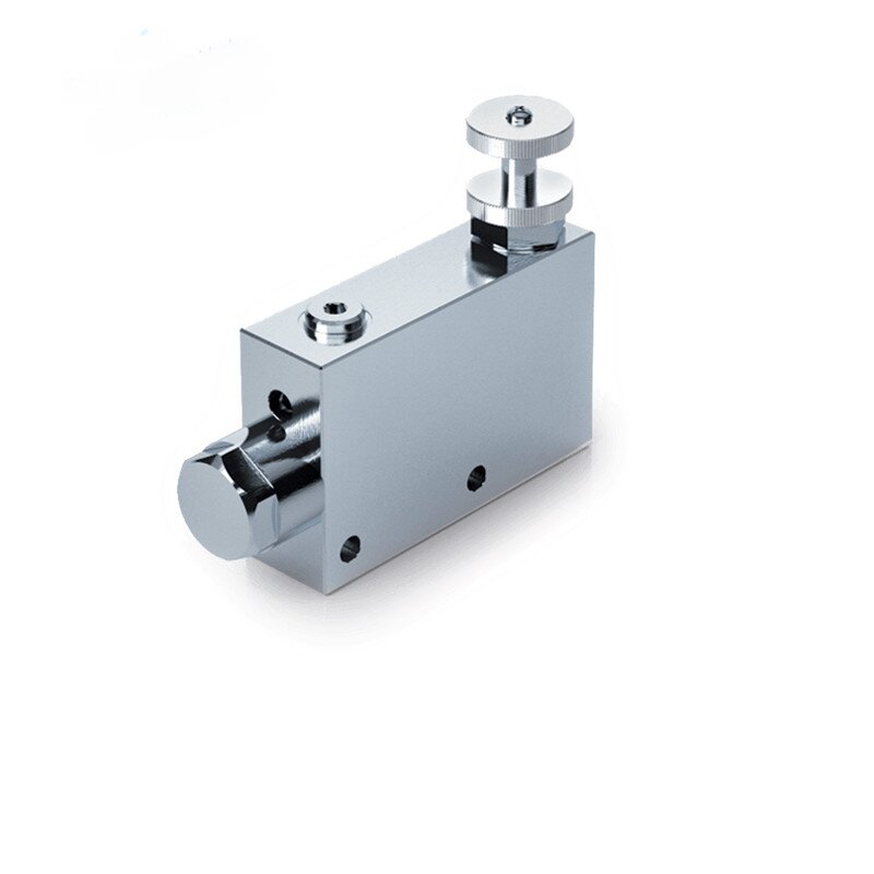
Flow control valves may also be called needle valves, throttle valves, flow regulators, orifice plates, throttle valves, or priority valves. By creating a pressure-drop limit in the loop, the flow rate can be controlled and thus the speed or acceleration of the load can be controlled.

![]()
The working principle of flow control valve mainly has the following types:
1. Throttle valve working principle
Change the flow area of the throttle: the throttle valve changes the size of the throttle through the axial movement or rotation of the spool to adjust the flow of fluid. When the spool moves in one direction, the flow area of the orifice increases, the resistance of fluid passing decreases, and the flow increases. On the contrary, when the spool moves in the opposite direction, the flow area of the orifice decreases, the fluid resistance increases, and the flow rate decreases.
Control flow according to flow formula: According to the general formula of orifice flow (where is flow, is the coefficient related to fluid properties and throttling shape, is the orifice flow area, is the pressure difference at both ends of the valve, is the index related to the throttling shape), when the pressure difference at both ends of the valve is certain, the flow is proportional to the throttling flow area, so the flow can be controlled by changing the throttling area.
2. Speed regulating valve working principle
Reducing pressure and throttling in series: The speed regulating valve is made of the differential pressure reducing valve and the throttle valve in series. The liquid flow first enters the pressure reducing valve, and then enters the throttle valve after reducing pressure.
Automatic adjustment of pressure difference: when the input oil flow rate is small, the oil pressure is low, the spool of the pressure reducing valve is at the lower end, and the pressure reducing throttle opening is large, which does not have a pressure reducing effect; When the input flow increases, the oil pressure at the outlet of the pressure reducing valve increases, and when the upward force of the oil pressure on the valve core is greater than the sum of the oil pressure and spring force at the upper end of the valve core, the pressure reducing valve core moves up and stabilates at the new position, the pressure reducing valve port decreases, and the pressure reduction begins, so that the pressure difference at both ends of the throttle valve orifice basically remains unchanged. In this way, no matter how the pressure difference between the two ends of the speed control valve changes, the flow through the speed control valve can remain stable.
3. Working principle of overflow throttle valve
Overflow and throttle in parallel: The overflow throttle valve is composed of an overflow valve and a throttle valve in parallel.
Pressure compensation control: it detects the pressure difference before and after the throttle valve, and uses the overflow of the relief valve to automatically adjust the inlet pressure of the throttle valve, so that the pressure difference before and after the throttle valve remains constant, and then realizes the stable control of the flow rate. When the load changes and the pressure difference before and after the throttle valve changes, the relief valve will adjust the relief flow accordingly to maintain the pressure difference before and after the throttle valve and ensure the flow through the throttle valve is stable.
4. Shunt collector valve working principle
Equal shunt and collector: shunt collector valve is mainly used to realize the synchronous action of multiple executive components. In the shunt working condition, the hydraulic oil enters from the inlet, after the shunt collector valve, according to the set proportion or equal amount of distribution to each outlet, respectively, to supply different executive components; In the collection condition, the oil discharged by each actuator is collected to the inlet of the collector valve in the same proportion or equal amount, and then flows back to the tank.
Spool force balance adjustment: its working principle is based on the spool force balance. Taking the diverter valve as an example, when the load of each branch is different, the flow area of each throttle is changed by the displacement of the valve core, so that the pressure difference of each branch is automatically adjusted to be equal, so as to ensure that the flow of each branch is equal or proportional.